Control Synthesis
Main concept
Control Synthesis is the final Assembly stage. Its job is to turn the collection of configured AlImps into a functioning application: it generates the processor firmware at both the AlImp and host levels, instantiates and interconnects the RTL components, and computes a static global schedule that makes every AlImp start its computation at the correct cycle. The output is an RTL framework of the target system — the interconnected AlImps, the host system, and the corresponding processor programs.
The stage has two parts, AlImp-level control and application-level control, tied together by a main control flow.
Main control flow
Both the host and the AlImps boot from empty memories, so program code is first loaded from an external source:
- A start-up module initialises the host processor and loads its program.
- The host wakes each AlImp by transferring its program code and releasing its reset; each AlImp performs local initialisation and then sends a mailbox notification back to the host.
- The host computes and distributes scheduling information to all AlImps. Using it, each AlImp activates at its designated cycle and runs its DRRA kernel.
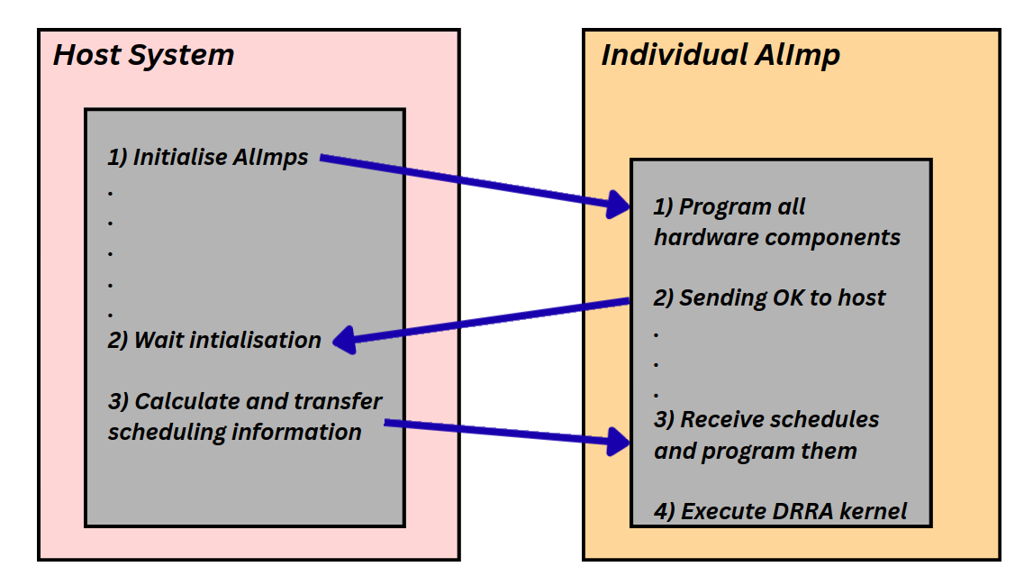 Host and AlImp cooperate over the mailbox: initialise → notify → receive and program schedules → execute the DRRA kernel.
AlImp-level control
Most AlImp hardware is common, but the processor memory size, the DRRA fabric and the communication modules vary per AlImp. This step provides the configuration needed to instantiate the parameterised RTL, and focuses on two things:
AlImp firmware. The firmware first programs the DRRA architecture
(drra_inst_loader()) and loads the TLB and transporter programs generated by
previous stages; it supports arbitrary numbers of TLBs/transporters and varying
program sizes. After initialisation it notifies the host through the mailbox and
waits for the schedule. The received timing values are programmed into the
synchroniser, which activates the AlImp processor and the transporters at their
scheduled cycles. The compute kernel() itself is generated by Vesyla; the rest
of the firmware is generated by Sylva, and the two are merged into one program.
Local synchronisation. Within an AlImp, only transporters need explicit synchronisation; their activation times are expressed relative to the AlImp processor's start time. For each transporter, the local activation time is derived from its absolute start time obtained in Transporter Code Generation, adjusted for fixed hardware delays and for the transporter's column position (the start signal is pipelined through intermediate hardware stages):
where T_{\mathrm{fire},tp} is the transporter's absolute start time and \mathrm{col} is its column relative to the left-most DRRA column. These local timing values are later combined into the global schedule.
Application-level control
This part generates the host firmware, formulates the timing model and determines the static schedule for the whole AlImp network.
Host firmware. The host initialises all AlImps, waits for their completion
messages, and runs the scheduler. Program initialisation is application
independent: all programs are stored in one flattened constant array, with
separate offset and size tables used to reconstruct each program section
(instruction text and data).
Timing model. The scheduler reads the 64-bit global timer, computes a
reference start time per AlImp, writes the per-AlImp start time and the
transporter offsets to the mailbox, and notifies the AlImp. The AlImp programs
these into its synchroniser and performs a blocking read whose release cycle is
the AlImp's start time. The crucial unknown is therefore the per-AlImp
schedule_time.
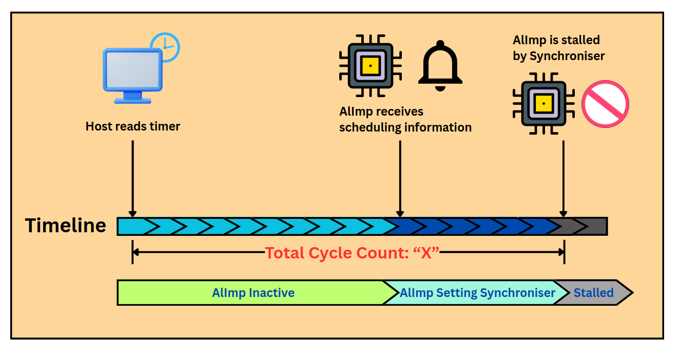 Timeline from the host reading the global timer, through the AlImp receiving and programming its schedule, to the stall that holds it until its start cycle.
void scheduler(void) {
    uint64_t cur_time = read_timer64();
    for (uint32_t i = 0; i < NUMBER_OF_ALIMPS; i++) {
        uint64_t ref_time = cur_time + schedule_time[i];
        add_start_time(i, ref_time);
        add_transporter_times(i);
        notify_mailbox(i, STATUS_START_TIME);
    }
}
Global synchronisation. Because the host programs AlImps sequentially in a loop, each AlImp becomes ready at a slightly different time. Sylva computes a ready time per AlImp, corrects it for any negative transporter offsets, and takes the worst case to find the earliest globally consistent reference time:
where T_{\mathrm{stall},i} is the cycle at which AlImp i enters its stall, T_{\mathrm{host}} the cycle at which the host reads the timer, \mathrm{relTimes}_i the transporter relative offsets, and T_{\mathrm{fire},i} the AlImp's firing time.
In practice these timing values (T_{\mathrm{host}}, the per-AlImp stall cycles)
are collected through RTL simulation: a temporary firmware with deliberately
large schedule_time values is generated to make the stalls observable, the
testbench records the relevant cycles, the final schedule is derived from the
equations above, and the firmware is regenerated and verified with the corrected
schedule.
Result
The result is a complete, simulatable RTL system: instantiated and interconnected AlImps, the host, the firmware for both processor levels, and a static schedule under which all AlImps execute correctly. See the Hardware Architecture page for the components being controlled.